Table of Contents
1D coin validators (placeholder)
Single slot 1D phones (and newer retrofit controllers by Elcotel, Protel, AT&T and others) utilized different coin validators – from mechanical 20A (with 47A electronic sensor module) to fully electronic ones – MARS LPV 226WE and AT&T 22A. The latter ones were backward compatible and all used a 15-pin D-SUB connector.
The goal of this page is to reverse-engineer the signal lines between the payphone controller and the coin validator.
Those coin validators detect only three types of coins (5ct, 10ct, 25ct). Electronic validators may or may not be able to detect more coins or deploy extended communication protocols, but this is out of scope for now. I would expect at least 5 wires needed: detection of 3 coins, positive and negative voltage supply. Reality might be more complex though…
Jump to conclusions if you don't need the whole story.
Analysis
I started looking at the 32A controller side, but the complexity of wiring and lack of documentation on this common controller (detailed diagrams) made it difficult.
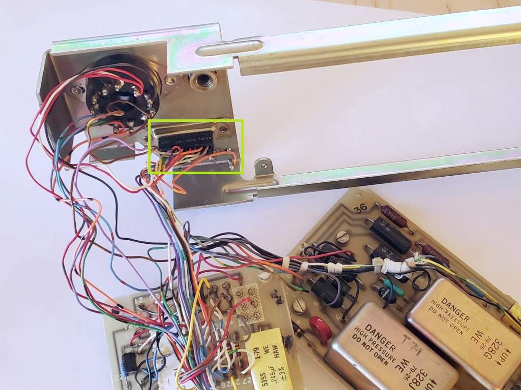
Quick look at the MARS controller chassis: looks promising, seeing three 100R resistors, they might be related to coin signal lines. Still kind of complex.
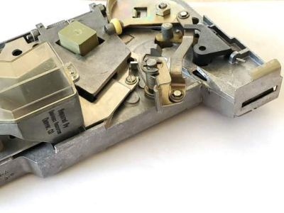
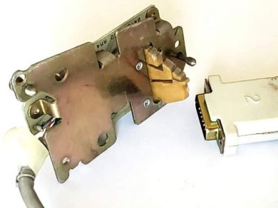
Let's check the original 47A signal module from 1979. Only 9 wires in use. Three inductive sensors as expected.
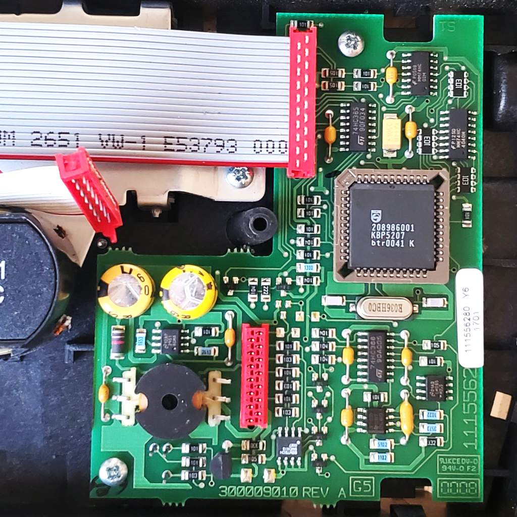
Circuit board is relatively simple, but the main chip – Motorola KS21625L7 – doesn't seem to be documented.
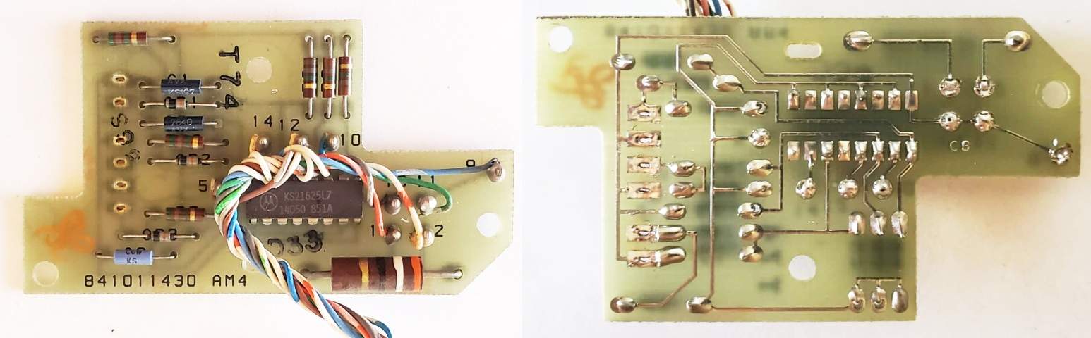
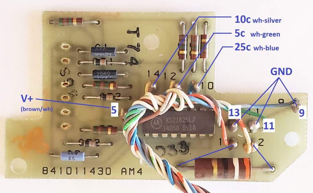
A moment later everything seems clear. Ground is present on three wires – pins 9,11,13. Pins 1,2 only connect to a 39R resistor (doesn't exist in MARS validators – it's open loop). Then we have a power supply and three coin signals pulled to ground (open collector).
Voltage provided by the controller: ######
Conclusion
WE 1D coin validator / signal unit pinout is as follows:
1-2   29 Ohm / 1W (mechanical validator only)


5     V+


9     GND


10    Quarter


11    GND


12    Nickel


13    GND


14    Dime
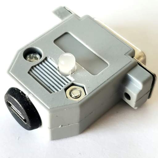
Now it's easy to build a portable coin validator tester. Three-color common-anode LED connected via a 100R resistor to V+ (5V supplied via USB-C connector), cathodes connecting to coin signal pins 10, 12, 14; everything installed in a D-SUB female plug. Recognition of each coin flashes different colors.